1st Oct, 2017
Display Area
Model
fx-5800P, fx-9860GII, fx-CG10/20 and fx-CCG50
Description
- fx-9860GII or fx-CG20/10 has Text Screen and Graphics Screen. Those 2 screens are switched to each other, and text and graphcs cannot be displayed in a single screen.
- Text Screen of fx-5800P has 4 lines and 16 columns display area. Text Screen of fx-9860GII and fx-CG10/20/50 has 7 lines and 21 columns display area.
- UNDOCUMENTED Graphics Screen of fx-9860GII has 127 pixel x 63 pixel display area. Graphics Screen of fx-CG20/10 has 379 pixel x 187 pixel display area.
Note
- UNDOCUMENTED For correct bitmap output with ViewWindow setup, user should be aware of the correct pixel numbers of graphics area. For example a bit map output should have problem if ViewWindow 0,126,0,0,63,0 is set instead of correct setup ViewWindow 0,127,0,0,62,0, See below in details;
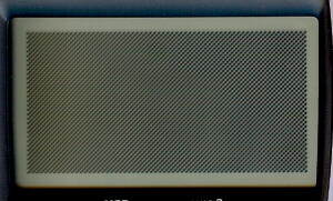
Example 1-1: Correct bitmap output as expected in code (fx-9860GII)
| Code | Result Image |
|
ClrGraph |
 |
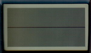
Example 1-2: Unexpected horizontal line appares with wrong ViewWindow seetup (fx-9860GII)
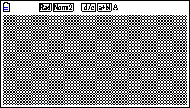
With fx-CG10/20/50, ViewWindow 0,126,0,0,62,0 and ViewWindow 0,126,0,0,63,0 gives similar but different results.
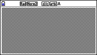
Example 2-1: Correct bitmap output as expected in code (fx-CG-10/20/50)
| Codes | Result |
|
ClrGraph |
 |
Example 2-2: Unexpected horizontal line appares with wrong ViewWindow setup (fx-CG10/20/50)
1st Oct, 2017
Vaiety of Coordinate Systems for Graphics
Modelfx-9860GII, fxCG10/20 and fx-CG50
Function
- Casio Basic provides variety of coordinate systems; Device Coordinate System and Logical Coordinate Systems.
- Device Coordinate System directly corresponds to pixeles of LCD. Left top pixel is pointed by cordinate (1,1) which means (first Row, first Column). Row is in vertical direction and only discrete (natural) number 1, 2, 3, ... is avaiable. Column is in horizontal direction and also only discrete (natural) number is available. With fx-9860GII maximum Row coordinante value is 63 and maximum Column coordinate value is 127. With fx-CG20 max Row value is 187 and max Column vaue is 379. Out of the min - max range or fractional number is set as parameter, Casio Basic returns ERROR.
- Device Coordinate System is automatically applied only at usage of Text, PlxOn, PxlOff, PxlChg and PixlTest commands. User cannot expressly set Device Coordinate System.
- There are 2 deferent ways to setup Logical Coordinate System, a Default Logical Coordinate System and ViewWindow Logical Coordinate System.
- UNDOCUMENTED Default Logical Coordinate System is automatically chosen when ClrGraph command runs. This coordinate system can be expressed by Xmin = -6.3, Xmax = 6.3, Xscl = 0.1, Ymin = -3.1, Ymax = 3.1 and Yscl = 0.1, where those 6 variables are automatically set with those above values. In stead of ClrGraph, following codes gives same resut; Cls:-6.3->Xmin:6.3->Xmax:-3.1->Ymin:3.1->Ymax (where -> is substitution command).
- Using ViewWindow command any coordinate system can be defined freely. We call this here as ViewWindow Coordinate System. In stead of ViewWindow command, setting 6 variables (Xmin, Xmax, Xscl, Ymin, Ymax and Yscl) results in same setup;
1st Oct, 2017
Control of Internal Curosr Row
Modelfx-5800P, fx-9860GII and fx-CG20
Function UNDOCUMENTED
- When ? (input), " " (output) or ◢ (output of value and pause) runs, input and output row is automaticallly controled. The input and output row start with top row of LCD and incremented at the time one of those commands is carried out. Once the row comes to bottom (4th row with fx-5800P or 7th row with fx-9860GII and fx-CG20/10) the row stays at the bottom.
- Only after 'clear text' command Cls (fx-5800P) or ClrText (fx-9860GII and fx-CG20/10) runs, the cursor row is reset back to top row.
- Run "" (no charactor within " ") once, then the internal cursor moves down to the next row.

